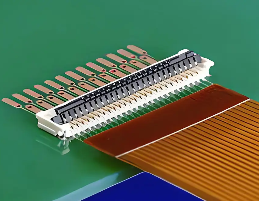
1. FPC is a flexible circuit board that can be folded and bent, usually used for connecting the upper and lower parts of flip phones, battery protection circuits, etc. In order to ensure the flatness of FPC, manufacturers usually flatten the FPC before shipping, and because FPC is flexible, it is difficult to use vacuum packaging. Therefore, during transmission and use, attention should be paid to ensuring the flatness of FPC and avoiding bending as much as possible

2. FPC generally consists of 1-2 layers, and multi-layer FPC is relatively rare The substrate and cover layer of FPC are generally made of polyimide, which is pressed and integrated with the copper foil. The thickness of some FPCs is marked by the thickness of the copper foil, such as 1.5OZ and 2.0OZ. Unlike PCBs, the opening of the cover layer on the copper foil is generally smaller than the area of the copper foil, while the Solder Mask area on the PCB is generally larger than the area of the copper foil. It should be noted that the FPC substrate and copper foil are bonded by resin, and in some cases, the resin may overflow and cause pad contamination, leading to solder leakage
3. The waste area of FPC generally adopts two processes. One is called Solid Copper, which covers the entire copper foil, and the other is called Cross Hatching The flexibility of FPC produced by Solder Copper process is relatively small, and it is relatively flat if not bent, but it is not easy to recover after bending The FPC with Cross Hatching process is the opposite
4. FPC requires support throughout the entire SMT process, usually made of synthetic materials that are not heat-resistant or anti-static. Some companies also use thin aluminum plates for support. The commonly used positioning method is to use high-temperature tape to stick the FPC to the support plate. However, it should be noted that the position of the tape should be as close as possible to the four corners and the middle of the longer edge of the FPC, which can prevent the FPC from warping. The thickness of the tape will also have a certain impact on solder paste printing, so the position of the tape should not be attached to the edges of densely packed components or around components with thin tube feet, and more importantly, should not be attached to solder pads
5. Due to the poor flatness of FPC compared to PCB and the influence of various factors such as support and tape, it is difficult for FPC to fully adhere to the mesh board during the printing process, which can cause problems in controlling the amount of solder paste. Based on my actual experience, I have two suggestions for the opening of the mesh board: firstly, for IC components with dense pins, the mesh holes of the mesh board should be narrowed and elongated as much as possible, and the mesh board should be as thin as possible. Practice has shown that inverted trapezoidal mesh holes are more advantageous for printing. Secondly, for chip components or connectors with large spans, the mesh holes should be enlarged as much as possible to avoid solder leakage caused by uneven FPC
6. As FPC requires support, the profile setting of the reflow oven must consider the heat absorption of the support plate during reflow soldering. Generally, it is recommended to set the temperature below the reflow oven slightly higher than above to ensure that the temperature of the support plate is similar to that of FPC and avoid cold soldering. In addition, the cooling air at the outlet should be strong to ensure that the temperature of the support plate drops to a safe temperature. Cooling fans can also be added at the outlet of the reflow oven
7. For the convenience of segmentation, the FPC and the edge are generally pre cut along the contour. The uncut part usually retains a layer of substrate (Micro Joint) and needs to be punched with stamp holes on it. Stamp holes not only facilitate segmentation but also prevent large burrs from being generated at the segmentation point. The connecting part can also ensure that the FPC does not lift during SMT, so Micro Joint should be retained at each incision in the FPC FPC cutting can be done manually or using specialized molds similar to punching machines